Missing All Hardware
I bought the Anycubic Kobra Neo from a seller on eBay who resells Anycubic returns as-is with no warrenty. These are not refurbished and I was warned they would be in an unknown condition (i.e., they do not inspect their returns).
It arrived and looked promising. The packing foam looked intact and every place that looked like it should have a thing had a thing.
But in the end it was missing all the hardware (screws and washers), half of the tools (hex key and wrench), a calibration tool, the IEC power cord, all paperwork, and the SD card.
The biggest problem was the hardware.
I made my way over to the Anycubic Kobra Neo Wiki where I found the assembly instructions which, thankfully, included the entire packing list. I needed:
- M3x8 (4)
- M4x6 (2)
- M4x16 (2)
- M5x25 (2)
- M5x45 (2)
- M5 spring washer (4)
These should all be socket hex head screws - and these are all available at Home Depot (so was the IEC cable). So I stopped by and about $15 later I had what I needed. Returning home, I performed the assembly and was able to power on the printer.
Connecting via USB
Since I did not have the SD card, I wanted to connect via USB. The printer has a USB-C port but it cannot read a USB drive from it - it seems it can only be used for external control.
I went back to the wiki and found the CH341 driver which I installed on my printer control computer (I have a dedicated mini computer for printer control to keep random software off my personal computer and isolated from the rest of the network).
After installing, I was able to see that it was using COM4 (you can see this in Device Manager in windows - look at the COM ports for the one with CH341 in the name) and now I would connect via Cura and Pronterface.
With this done I sent a test print … and it was horrible.
Printhead way too high (Z offset adjustment)
I should have taken a picture of how bad this was - but you’ll just have to imagine it. The first print was just strings of glop dropped from about 1.5-2mm above the bed. I was printing a 50x50x0.20 test print and it looked like I was just running the extruder randomly while playing with the X/Y controls.
Given my other printer is a P1S, I haven’t actually had to deal with this before so I did a little reading to understand that the problem was Z axis height. This is where the missing SD card is a bit of a pain. Anycubic includes a Z-axis adjustment process in the manual but it requires some pre-loaded gcode on the card. Since I didn’t have that, and they don’t link it on the wiki, I basically tried to recreate the process by hand.
Since the default of 0 was way too high, I started by going to -0.90 and doing 10x10mm test prints at 0.9, 1.0, 1.1, and 1.2. The results were this:
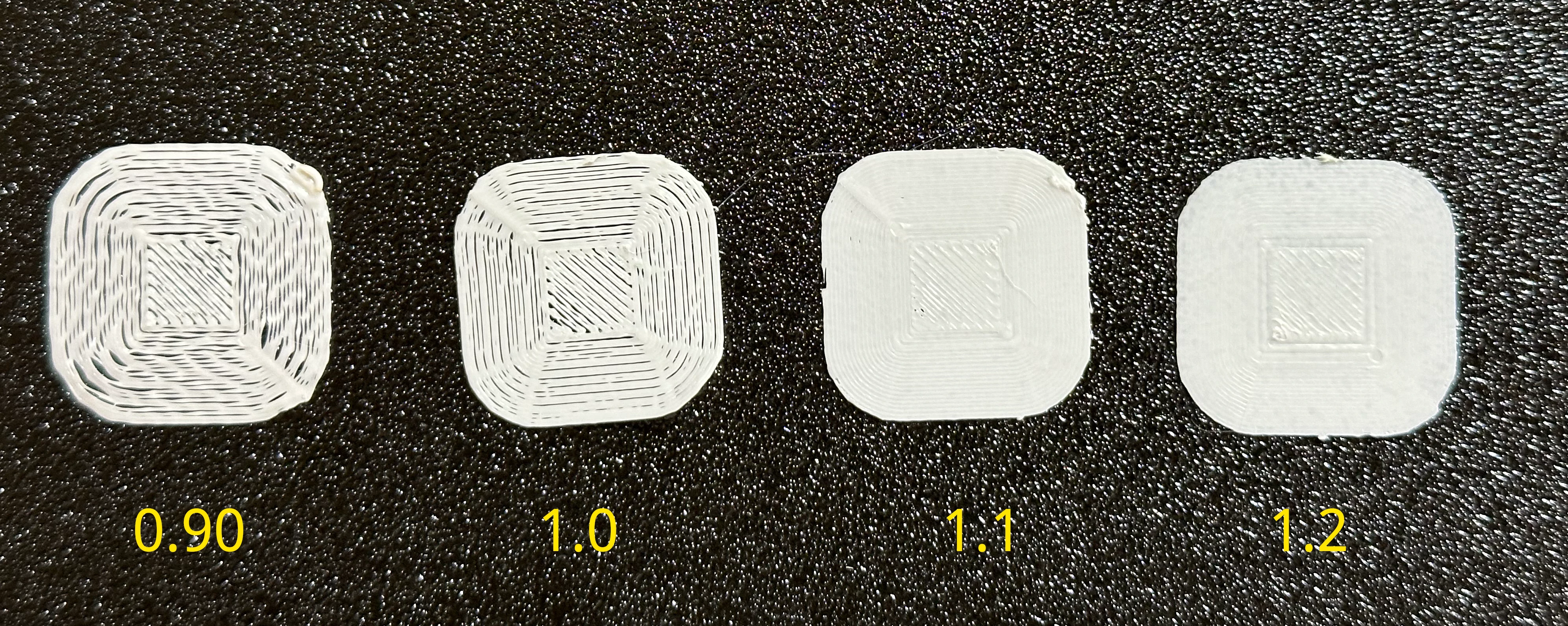
After this I fiddle a bit more and finally ended on -1.14 as my height adjustment and for now it’s fine - I’ll move on to the next steps.
Filament extruding at wrong speed (E-step calibration)
While doing some test prints I noticed there was some under extrusion going on - you can see it above in the z-axis adjustment section.
I decided to do an e-step adjustment to make sure the right amount of filament is coming out. To do this, I followed the process described at all3dp.com.
The following was all done in Pronterface connected to the printer via USB.
- Send the M503 command to get the settings - this returned (among many other things) this information:
echo:; Steps per unit:
echo: M92 X80.00 Y80.00 Z400.00 E390.00
So we have 390 e-steps per mm of filament.
-
Use a ruler and sharpie to add a line to the filament exactly 120mm above the print head.
-
Send the following:
M83;
M18 S60;
M109 T0 R200;
G1 E100 F100;
G4 S90;
M104 S0;
Now, this is where things didn’t work. The printer returned an error on the line G1 E100 F100; complaining that the values were out of range.
So I used the UI to set the extrude length to 100, the speed to 100 (this is mm per minute), and then hit the extrude button manually - and that worked fine.
- Measure and calculate the new value
With that done I measured from the top of print head to my line (it was drawn at 120 but I only sent 100), and found there was a 30mm gap. So it only sent 90 of the 100 I asked for.
Since we saw earlier that there are 390 e-steps per mm - it did exactly 39,000 steps (390 * 100). But it acted like it only did 35100 (390 * 90). So we can now divide 39000 / 90 and we get 433.3.
- Update the setting
To update the setting I simply send the following gcode:
M92 E433.3
M500
That set the new value to 433.3 and then saved it.
- Verify
I re-ran the extrusion test by marking the filament at 120mm and then extruding 100mm and this time when I meausured, it was right at 20mm remaining - so I asked for 100 and I got 100.
FYI - Updating the firmware resets Z-axis and e-steps
I updated the firmware from 1.2.8 to 1.3.3 and noticed immediately that z axis was reset to 0 but it took a little more poking to realize that e-steps were also reset from 433 to 390 causing significant under extrusion.
Just something to keep in mind when you update.